I have purchased 2 different WiFi relay modules on Aliexpress, you can find description of my experiments and experiences in this article

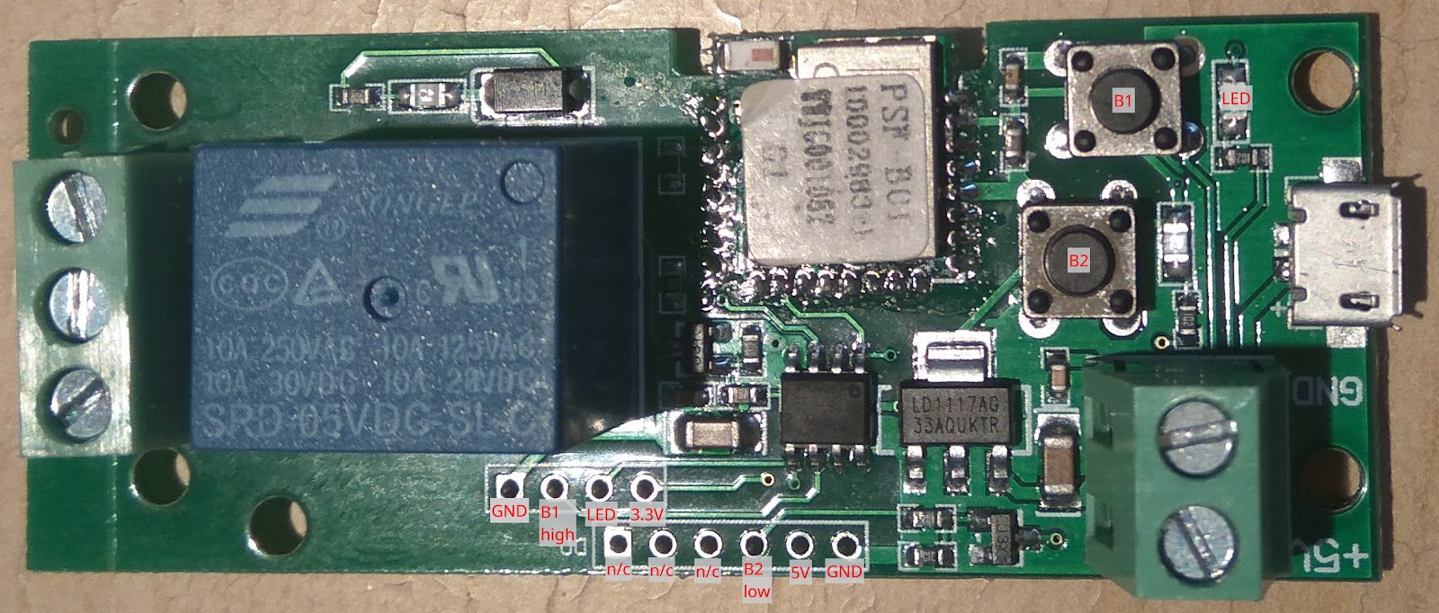
5V One Channel Inching /self-locking PSF B01 5V relay using module PSF-B01 (letter B indicates there is WiFi antenna soldered directly on the board (see small white rectangle in the top left corner)
I have found description for ITEAD PSF-B85 only, there is ESP8285 1MB integrated inside the module
- !!! WARNING !!! you can see many wrong / confusing photos on the internet describing 4 PIN pinholes as Tx, Rx pins
- !!! WARNING !!! THERE ARE MANY VISUALLY SIMILAR BOARDS TO THIS but different module on the board and different schematics
- There is another chip/processor yet on this board, called “Misterious CHIPâ€
- Itead is offering such a device as “1 Channel Inching /self-locking WiFi Wireless Switch 5V 12Vâ€
- I did buy it on Aliexpress, it came with original Itead SW; Sonoff app eWelink was communicate with the device without any single issue
- it was possible to update original software using build in OTA to the version 3.0.
Flashing firmware:
I have found this beautiful article about how to flash similar raley board to ESPruna firmware
- Solder wires to the pins 22 (TX) and 21 (RX), 20 (GND) (don’t be confused by the Tx Rx description of pinholes in the article). Some people do not solder Tx and Rx and are using POGO pins or wires instead and holding them by hand during the flashing procedure
- connect them to the Tx, Rx, GND on your USB programmer (ESP Tx <=> USB Rx, ESP Rx <=> USB Tx)
- press and hold button B2 (button closer to the green screw terminal)
- connect the 5V USB power supply
- release B2 (both red LEDs should to light)
- now the ESP should be in the programming mode
- First, I was trying to flash Tasmota firmware (the relay original firmware here ), but the relay was not stable and I didn’t find the way how to set it up properly using “tasmota generic module options†(see below my setting for ESP 01S relay)â€
- in the article mentioned above, there is great description how to build the custom ESPurna firmware using Atom+PlatformIO – in my case the first try was returning many errors during compilation
- The reason was the the ArduinoJson library version 6 was not supported by ESPurna in the time of writing this article (March 2019) . Thanks to the ESPurna forum I have found the solution relatively fast. It was necessary to modify platformio.ini by replacing
by
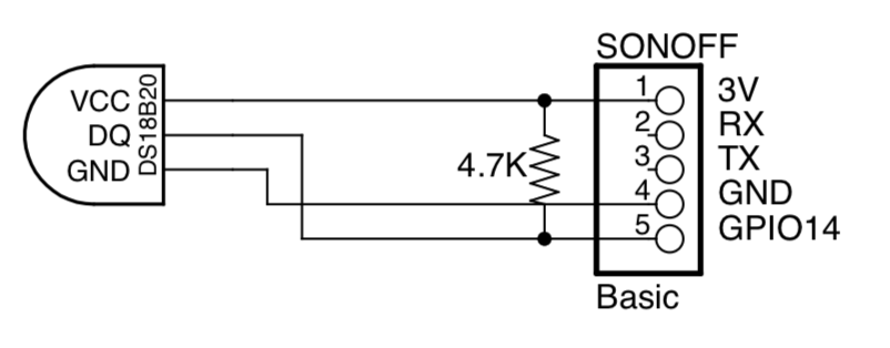
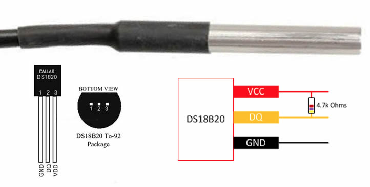
As I wanted to use the DS18B20 to monitor temperature, it was necessary to change the /config/sensors.h as well and solder wires according to the pictures below
For ESPurna configuration see the detailed description mentioned in the article or ESPurna wiki.
Flashing binary
esptool.py –port /dev/ttyUSB0 flash_id is showing ESP8285 on the board
ESP-01S relay (ESP8266 5V WiFi relay module)
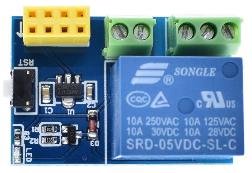

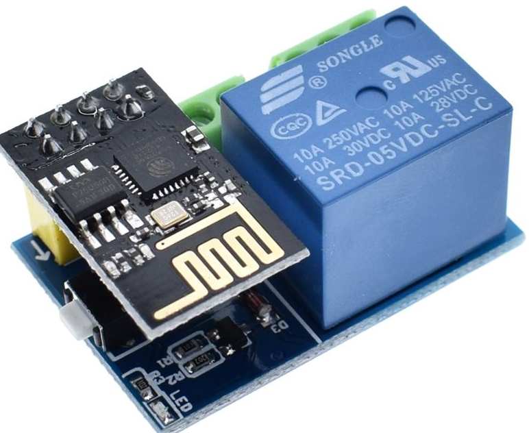

- !!! WARNING !!! THERE ARE MANY VISUALLY SIMILAR BOARDS TO THIS RELAY BOARD but different schematics
- when I have received it from Aliexpress (US $2.09 including ESP-01S), module was not working (I have found other people had the same issue)
- There are two culprits of this:
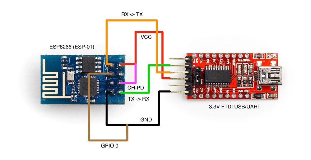
- “CH_PD” is not set to HI (3.3V) as actually required. Usually this is done with a 10K resistor or directly to 3.3V, I have connected CH_PD pin directly to the 3.3V
- The resistor R2 (10k) which is connected between the terminal GPIO0 to ground. This ensures that the GPIO0 is always pulled to ground, which actually places the ESP-01 in program mode (flashing). After soldering out (removing) R2, the module ran smoothly.


esptool.py –port /dev/ttyUSB0 write_flash -fs 1MB -fm dout 0x0 sonoff.bin
- After flashing firmware, I have connected DS18B20 to the GPIO2 as well (see the diagram)
- Than it was necessary to set up Tasmota as generic module, GPIO0 as Relay1 (21), GPIO2 as DS18x20(4)
- OTA upgrade works flawlessly as well
Retrieving the temperature via HTTP
http://sonoff-ip/cm?user=<USER>&password=<PASS>&cmnd=status%2010
The temperature information will put published by MQTT to the
tele/<SONOFFDEVICE>/SENSOR in the format of:
“Time”:”2018-06-14T07:56:34″,”DS18B20″:{“Temperature”:21.9},”TempUnit”:”C”}
Setting interval at which the sonoff will report it’s status:
Display current interval: TelePeriod
Set interval: TelePeriod <seconds>
You can change PulseTime by typing “PulseTime 30” in the Console at the Webinterface.